4.6 Data Flows
This section defines architectural data structures and the flows in which these structures move through the boot over time.
4.6.1 Silicon Policy Flow and Rules
4.6.1.1 Silicon Module Provides Default Silicon Policy Data
One silicon policy data structure is created per silicon module. The data structure should only contain data. Functions should not be used in silicon policy data.
When a silicon module installs this policy data, it should consider the most common usage as the default policy data. Therefore, a board module must only update non-default values instead of all fields.
This silicon code may expose the APIs below.
An API to initialize all policy data to the default value, based upon the current silicon.
An API to tell silicon code that all policy data have been updated, and they are ready to consume.
Library |
Interface |
Definition Location |
Producer |
Consumer in FSP Boot Path |
Consumer in EDK II Path |
|---|---|---|---|---|---|
| SiliconPolicyInitLib | SiliconPolicy InitPreMemory |
Silicon | Silicon | FspWrapper PlatformLib |
Platform |
| SiliconPolicy DonePreMemory |
Silicon | Silicon | FspWrapper PlatformLib |
Platform | |
| SiliconPolicy InitPostMemory |
Silicon | Silicon | FspWrapper PlatformLib |
Platform | |
| SiliconPolicy DonePostMemory |
Silicon | Silicon | FspWrapper PlatformLib |
Platform | |
| SiliconPolicy InitLate |
Silicon | Silicon | FspWrapper PlatformLib |
Platform | |
| SiliconPolicy DoneLate |
Silicon | Silicon | FspWrapper PlatformLib |
Platform | |
| SiliconPolicyUpdateLib | SiliconPolicy UpdatePreMemory |
Minimum Platform / Silicon |
Board | FspWrapper PlatformLib |
Platform |
| SiliconPolicy Update PostMemory |
Minimum Platform / Silicon |
Board | FspWrapper PlatformLib |
Platform | |
| SiliconPolicy UpdateLate |
Minimum Platform / Silicon |
Board | FspWrapper PlatformLib |
Platform |
Table 24 Silicon Policy Libraries
NOTE: A general guideline is that pointers should not be used in policies that persist across the CAR to permanent memory boundary as the pointer addresses will become invalid. Pre-memory only and post-memory only policies are not affected by the memory transition. A pre-memory policy installation PEIM should only be used for policies that must be updated in pre-memory for early use by silicon code. The post-memory policy installation PEIM can be compressed and does risk pointers becoming invalidated due to the memory transition.
The policy configuration HOBs are inherently passed to DXE, so a silicon DXE module can locate and install a policy protocol for a particular policy if it is used in DXE.
4.6.1.2 Board Module Silicon Policy Data
Using the SiliconPolicyUpdateLib, the board package may reference a variety of sources to obtain the board-specific policy values, including but limited to the following common sources.
PCD database
UEFI Variable
Binary Blob
Built-in C structure
Hardware information
4.6.1.3 Board Module Silicon Policy Update Completion
After policy configuration is completed, the board may indicate that the policy is configured with board-specific actions in the SiliconPolicyDonePreMemory ( ) API in SiliconPolicyInitLib.
4.6.1.4 Non-Intel® FSP Policy Data Flow
The SiliconPolicyPeiPreMemory module in the minimum platform package will invoke the following policy configuration functions in the given order.
- BoardPreMemoryInit ()
- SiliconPolicyInitPreMemory ()
- SiliconPolicyUpdatePreMemory ()
- Minimum platform: Minor update of relevant options
- Fully featured platform (Stage VI and greater): Full update for all platform features
- SiliconPolicyDonePreMemory ()
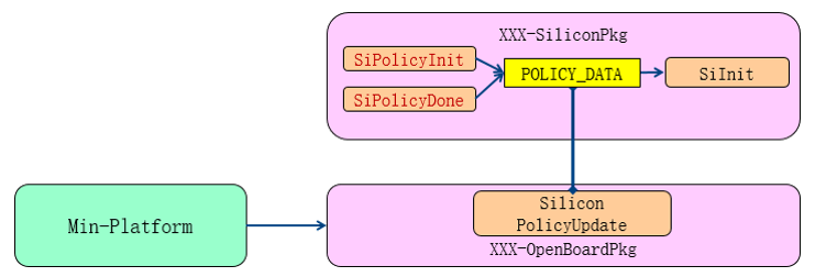
Figure 6 Non-FSP Policy Data Flow
4.6.1.5 Intel® FSP Policy Data Flow
- UpdateFspmUpdData (Upd)
- SiliconPolicyInitPreMemory ()
- SiliconPolicyUpdatePreMemory ()
- Minimum platform: Minor update of relevant options
- Fully featured platform (Stage VI and greater): Full update for all platform features
- SiliconPolicyDonePreMemory ()
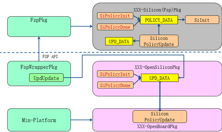
Figure 7 FSP Policy Data Flow
4.6.2 HOB Output
Intel® FSP HOB to PEI HOB transition
In an Intel® FSP API mode boot with an EDK II wrapper, the system will have two HOB lists - one maintained in the FSP PEI environment and the other in the FSP wrapper PEI environment. The FSP wrapper environment is responsible for converting data from the FSP HOB to a PEI HOB. These HOBs are platform-specific; examples include the SmbiosHob and GraphicInfoHob.
PEI HOBs for Phase Handoff to DXE
4.6.3 MTRR Configuration Settings in Post-Memory
The system MTRR settings are typically configured in two locations after permanent memory initialization.
After permanent memory installation
At this point, cache attributes are set for PEI memory usage. This specification does not require any particular MTRR configuration, as it is ultimately dependent upon platform goals such as functionality and performance given the device and storage technologies present on the platform. The most common ranges configured are the default memory setting as UC, the DRAM region as WB, and the SPI flash MMIO region as WP. These settings are usually applied in a memory installation notification function or a PEIM shadow. The architecture requires that the settings be applied in the board package.
Prior to DXE IPL
At this point PEI execution has completed and control is transitioning to the DXE phase. The MTRR settings are typically modified to prepare for the DXE environment. The most common ranges configured are the default memory as WB, the TSEG (SMRAM) region as UC, and MMIO as UC. These settings are usually applied in an end of PEI notification function. The architecture requires that the settings be applied in the board package.