2.4 Typical Flash Part Layout
While a flash part layout is specific to a given platform, there are some generalizations that apply. The SEC and PEI code is typically put into a "RECOVERY" location, while all remaining sections are put into the "MAIN" location. The MAIN section may be compressed for size optimization, provided the PEI or SEC code contains appropriate decompression drivers. The PI specification defines only standard EFI compression; if other compression mechanisms (or verification mechanisms, such as CRC32) are required, then both the tools for creating a compressed image and a library for decompressing the image must be provided. These non-standard compression, encryption, signing or verification mechanisms are applied to a GUIED encapsulation section. Each method needs a unique GUID, however the methods may be applied to images more than once per FD image. This is done in order to facility recovery and updates (called capsules). Other areas in flash may be reserved for non-volatile (NV) data storage, fault tolerant working (FTW) space or vital product data (VPD) areas. These other regions are not defined in the PI specification, and implementation is left to the platform integrator. The reference design Nt32 Platform emulation environment contains a virtual flash device. The content within this virtual FD is laid out per Figure 4.
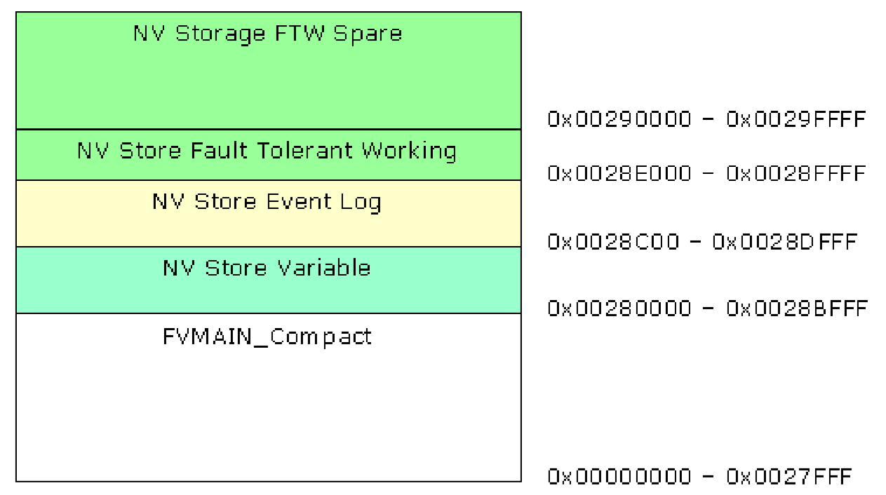
Figure 4 NT32 Flash Device Layout
Figure 5 represents a typical IA32/X64 FD layout, where SEC and PEI code is
located in the FV Recovery section, and the remaining drivers are located in a
GUIDED encapsulation (compressed) section designated as FVMAIN_Compact.
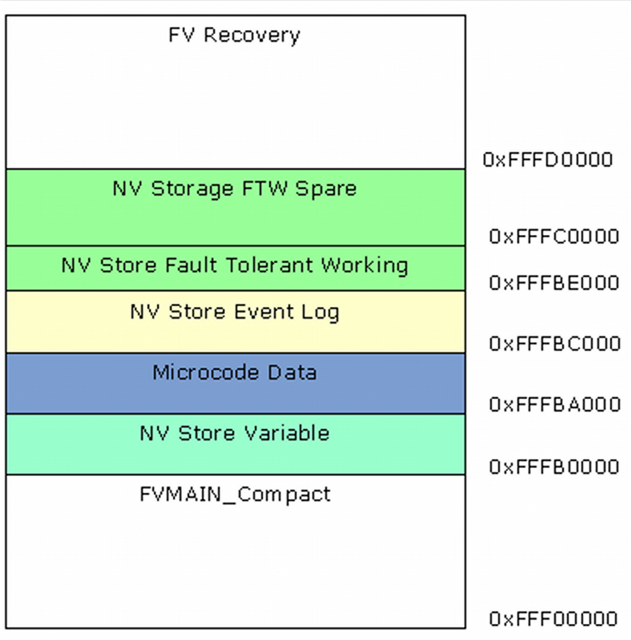
Figure 5 Typical IA32/X64 Flash Device Layout
Figure 6 represents a typical IPF FD layout.
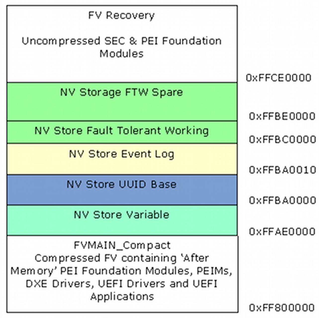
Figure 6 Typical IPF FD Layout
All of these layouts assume only one flash device, with the virtual memory addresses listed for each section within the FD.
Note: More than one flash device may be present within a platform, so the images may be split over multiple devices.