3.1 Overview
The objective of Stage I is to provide a foundation for more complex development in later stages. The board should implement a board-specific minimal code path capable of firmware debug output. Basic debug capability serves as a base for development activities in later stages. As Stage I is inherently foundational to product execution it may include more content and complexity than the functionality strictly required for debug output.
3.1.1 Major Execution Activities
- Establish temporary memory.
- Perform pre-memory board-specific initialization.
- Board detection
- GPIOs
- Serial Port initialization (Example: SIO, HSUART)
It is not necessary for the developer to fully configure GPIO at this time. The only required board configuration is that necessary to reach system debug activities.
3.1.2 Main Control Flow
Stage I is contained within SEC and PEI phases. Code must not be compressed and content must be capable of being mapped to memory by hardware or other firmware.
The high level control flow is described in the diagram below.
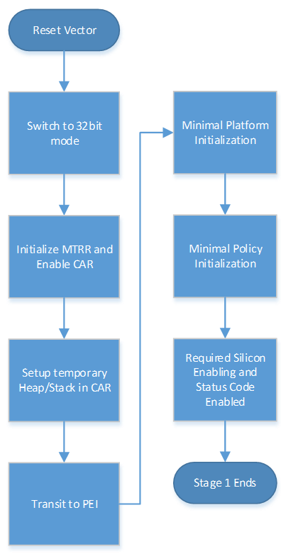
Figure 4 Stage I Main Control Flow
These activities do not map 1:1 to the required functions. Some of this flow is already well defined by UEFI or EDK II specifications. The following details are focused on the Platform, Silicon, and Board interactions, and minimal requirements for structure, consistency, and portability.