6.1 Overview
The objective of Stage IV is to enable a minimal boot path that successfully boots a commercial operating system such as Linux or Windows, with UEFI interfaces exposed to the OS implemented in compliance with the UEFI specification. The minimal boot path only involves functionality necessary to load the OS to a state where a user may begin performing more complex interactions. This involves successfully reaching an environment that allows the user to launch applications. The stage does not include support for all applications that, for example, may require certain CPU or GPU features enabled. Nor does it require any further support, including but not limited to device and system power management, full hardware performance support enabled, system reset support, etc.
Any additional functionality is classified as an advanced feature. Those features are collectively enabled in Stage VI.
6.1.1 Major Execution Activities
Stage IV Modules |
|---|
| Minimum ACPI table initialization |
| Additional input, output, and storage support based on platform and operating system requirements |
| SMM |
| Perform ACPI enable/disable |
| Kernel debug support |
| UEFI variable support |
6.1.2 Main Control Flow
Stage IV introduces additional functionality to meet the minimal requirements for a UEFI-compliant operating system. Much of the support required will be performed during the DXE phase interleaving Stage IV control flows with pre-existing control flows from Stage III. A minimum set of ACPI tables, namely RSDT, FACP, FACS, FADT, MADT, HPET and DSDT, need to be initialized and published. If there are alternative and/or additional operating system expectations such as full DeviceTree support, that should be enabled to allow the operating system to be loaded.
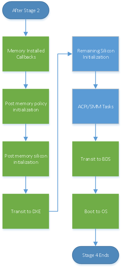
It is recommended that only the mandatory boot option devices are connected in BDS to minimize complexity and boot time in the minimal execution path to the operating system. In the flow diagram below, the left half is identical to the functionality enabled by Stage III prior to entering the BDS phase. It is expected that the Stage III components are reused to complete Stage IV tasks.
The green blocks in Figure 9 Stage IV Control Flow reuse the existing blocks from Stage III.